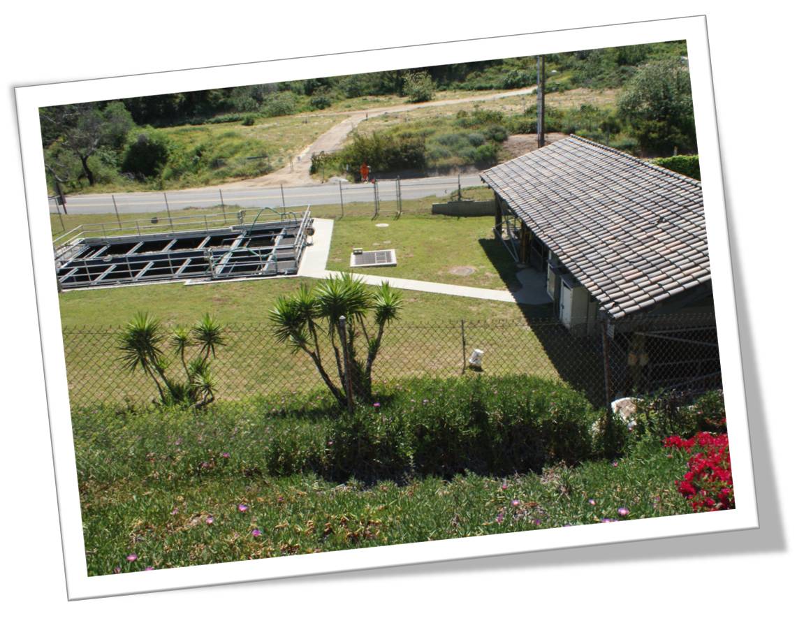
 TYPE: Secondary wastewater treatment facility
CAPACITY: 51,000 gpd of domestic wastewater
TREATMENT PROCESSES:Comminution, extended aeration biological treatment, secondary clarification, sand filtration, and chlorine disinfection.
The treated wastewater is discharged into seepage pits for disposal.
BACKGROUND
The Malibu Water Pollution Control Plant (WPCP) is located at 3620 Vista Pacifica Street, Malibu, California. The Los Angeles County Department of Public Works operates and maintains the Malibu WPCP. The plant treats domestic wastewater on behalf offour condominium complexes in the City of Malibu: 48-unit complex at Maison DeVille, 104-unit complex at Malibu Canyon Village, a 17-unit complex at Vista Pacifica and a 22-unit complex in the City of Malibu.
WASTEWATER TREATMENT PROCESSES
The Malibu WPCP is a secondary wastewater treatment facility with filters. It was designed to treat 51,000 gpd of domestic wastewater. Treatment processes include comminution, extended aeration biological treatment, secondary clarification, sand filtration, and chlorination. The treated wastewater is discharge into seepage pits for disposal. Figure 3-1 is a Flow Diagram of the treatment process. Following is a brief discussion and description of the treatment plant processes.
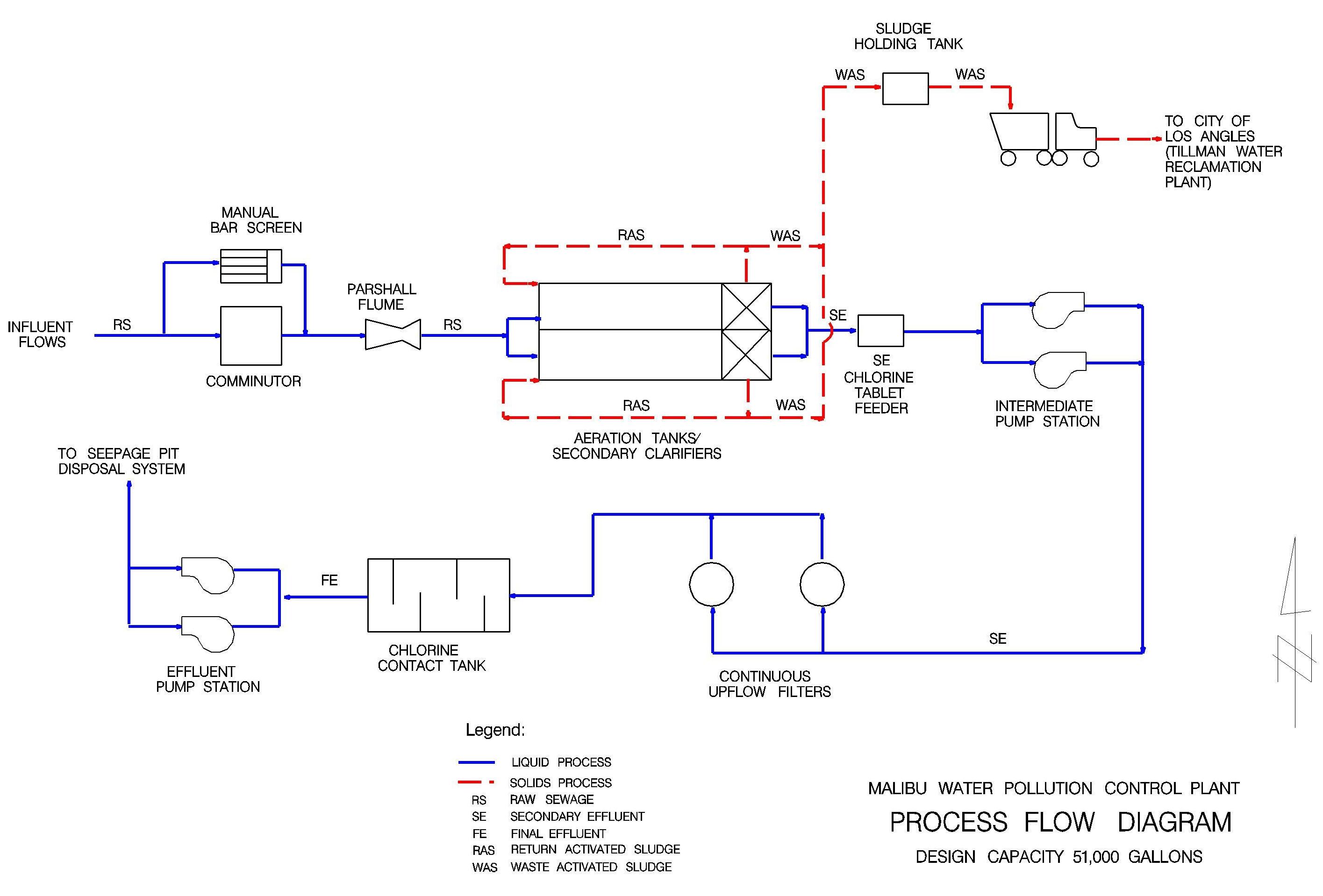
Figure 3-1. Flow Diagram
Preliminary Treatment
Preliminary treatment consists of an influent channel, comminutor and flow meter (Photo 3-1). The flow enters the treatment plant through an 8-inch gravity line into the influent channel and flows to the comminutor. The comminutor cuts and shreds large pieces of material into smaller pieces. This minimizes clogging and plugging problems in the downstream treatment processes. A by-pass channel with a manual bar rack is provided if the comminutor needs to be serviced. The influent flow is measured by a 2 inch parshall flume downstream from the comminutor and the bar rack.
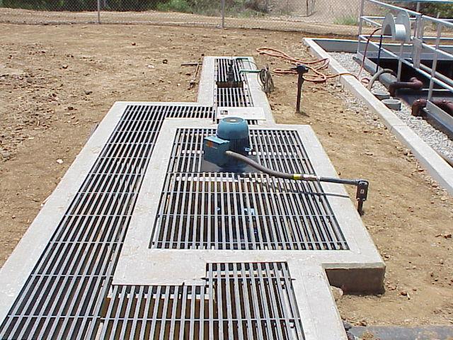
Photo 3-1. Headworks with comminutor
Secondary Treatment
Secondary treatment consists of a dual-train extended aeration tanks followed by secondary clarifiers (Photo 3-2). The wastewater proceeds from the preliminary treatment by gravity to the aeration tanks where the flow is aerated by course bubble diffusion. The aeration tanks provide a location where biological treatment of the wastewater takes place. In these tanks, microorganisms remove organic material from wastewater and form settleable solids. After the aeration tanks, the flow enters the secondary clarifier basins where the solids are settled and pumped by airlift pumps to either the aeration tank (return activated sludge) or to the sludge holding tank (waste activated sludge).
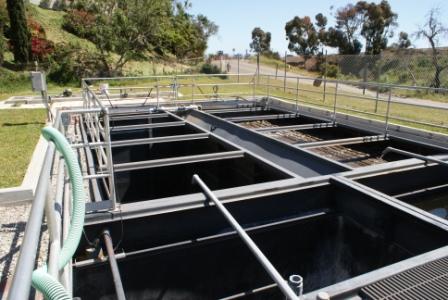
Photo 3-2. Extended Aeration Tanks with Secondary Clarifiers
Filtration
The secondary effluent is pumped into 2 continuous upflow filters (Photo 3-3). As the water rises through the filters sand media, the suspended matter is removed. The filters are continuously cleaned by air lifting the sand from the bottom and redistributing the sand to the top layer. The filters were not designed to produce a tertiary effluent quality. The main function of the filters is to enhance the percolation of the effluent into the seepage pit disposal system.
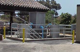
Photo 3-3. Filters
Disinfection
The filtered effluent flows to the chlorine contact tank. A calcium hypochlorite tablet feeder (Photo 3-4) dispenses the disinfecting agent (chlorine), which kills microorganisms in the filtered effluent.
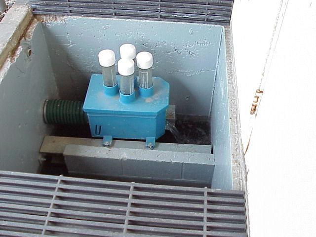
Photo 3-4. Chlorine Tablet Feeder
Effluent Disposal
Following disinfection, the final effluent is discharged to a seepage pit disposal system. The effluent is disposed in 20 seepage pits, 12 of which are in an eastern disposal area and 8 of which are in a western disposal area.
Sludge Disposal
Sludge generated from the plant is pumped from the sludge holding tank. The sludge is hauled in tanker trucks to the City of Los Angeles-owned Tillman Water Reclamation Plant for treatment and disposal.